Description
SBH15-M series amorphous alloy core transformer is made according to Chinese standard, equals to IEC standard. No-load loss of this series transformer is 75% less than that of CRGO distribution transformer.
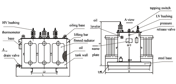
Structure features
-Amorphous alloy is a new strip material which has no crystal structure and so its magnetizing power is small, high resistivity, low eddy current loss.
- Core is of wound core structure, three-phase 5-column type, section is rectangular.
- Coil is rectangular, HV winding is wound by enameled wire; LV winding is wounded by foil, increased short-circuit throughput!
- Transformer connecting symbol adopts Dyn11, avoiding influence by high harmonic, stronger un-balanced load resisting capability.
- Vacuum oil filling avoids gas in windings completely
- Deletes oil conservator, adopts fin type radiator for cooling
Performance Parameters
|
Rated voltage: 6, 6.3, 10, 20 / 0.4KV |
|
||||||||
|
Rated tapping range: ± 5% or ±2×2.5% |
|
||||||||
|
Rated frequency: 50Hz (60Hz can be specially ordered) |
|
||||||||
|
Connecting symbol: Dyn11 |
|
||||||||
|
Rated Capacity (kVA) |
No-load loss (W) |
No-load current (%) |
Load loss (W@ |
Short-circuit impedance (% @ |
Weight (kg) |
Dimension (mm) L x W x H |
|||
|
50 |
43 |
1.3 |
870 |
4 |
460 |
1035 |
600 |
925 |
|
|
80 |
60 |
1.1 |
1250 |
600 |
1150 |
600 |
980 |
|
|
|
100 |
75 |
1 |
1500 |
660 |
1090 |
755 |
985 |
|
|
|
160 |
100 |
0.7 |
2200 |
920 |
1290 |
710 |
1040 |
|
|
|
200 |
120 |
0.7 |
2600 |
990 |
1220 |
885 |
1050 |
|
|
|
250 |
140 |
0.7 |
3050 |
1195 |
1370 |
920 |
1100 |
|
|
|
315 |
170 |
0.5 |
3650 |
1335 |
1265 |
1045 |
1085 |
|
|
|
400 |
200 |
0.5 |
4300 |
4/4.5 |
1585 |
1390 |
1180 |
1130 |
|
|
500 |
240 |
0.5 |
5150 |
1765 |
1390 |
1120 |
1195 |
|
|
|
630 |
320 |
0.3 |
6200 |
4.5 |
2400 |
1520 |
1185 |
1355 |
|
|
800 |
380 |
0.3 |
7500 |
2950 |
1885 |
1215 |
1470 |
|
|
|
1000 |
450 |
0.3 |
10300 |
3500 |
1955 |
1310 |
1565 |
|
|
|
1250 |
530 |
0.2 |
12000 |
4100 |
2025 |
1310 |
1675 |
|
|
|
1600 |
630 |
0.2 |
14500 |
5550 |
2535 |
1345 |
1830 |
|
|
|
2000 |
750 |
0.2 |
17400 |
5 |
6120 |
2595 |
1595 |
1985 |
|
|
2500 |
900 |
0.2 |
20200 |
5 |
8600 |
2950 |
1685 |
2500 |
|
|
|
|
|
|
|
|
|
|
|
|
|
Notes |
1. Short-circuit impedance of 400/500 KVA transformers @ 10KV and less is 4%; that @ 20kV is 4.5%. |
|
|||||||
|
2. |
|
||||||||
|
3. Special sizes or requirements can be discussed and special designed. |
|
||||||||
Insulation Level
|
Voltage Class (kV) |
Max. Effective Voltage (kV) |
Rated short-duration frequency voltage (kV/min) |
Rated full-wave peak lightning impulsive voltage (kV) |
|
≤1 |
≤1.1 |
5 |
/ |
|
6 |
7.2 |
25 |
75 |
|
10 |
12 |
35 |
95 |
|
20 |
24 |
50 |
120 |